A Mathematical Model of a Sagging Floor.

The simplest model of a sagging floor is essentially a simply-supported beam with a uniformly distributed load (representing the flooring it supports). Below, this model is used to calculate the difference in length of the floor before and after load.
Floors resting on wooden joists tend to 'sag' or be deflected downward. This deflection of course depends on several factors, such as the stiffness of the lumber (it's modulus of elasticity), it's dimensions (area moment of inertia of cross section), and the weight of the floor (the force distributed over the beam).
Luckily, for floors with joists supported on either end (and no center support) we have a simple analagous model: a simply supported beam. That is, a beam constrained on one end and supported from below (but allowed roll in the x-direction) so that it doesn't fall (or, move in the y-direction).

What we're interested in then is the deflection, or how far from flat, the beam is with the load applied. Luckily, this is a solved problem and one of basic structural engineering.
Deflection of a Simply Supported Beam (Under Uniform Load)
As mentioned before, we consider here a beam supported from below on both ends (and constrained to move by translation on one entirely). We then take the flooring to be a uniform load, since flooring is generally a uniformly distributed mass itself. In such a case, we have the following model for the deflection, where \(x\) is the distance from one support:
Let's plot this function to get a feel for it:
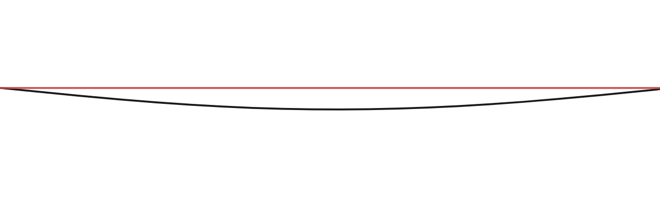
A Working Model
In this case, we don't really care to look up the elastic modulus of dimensional lumber and calculate moments of inertia. In the field, a more manageable quantity would be the deflection at the midpoint (or any other point for that matter). Such a quantity, along with the total length of the joists (the span) should be all that are required to solve for the corresponding function of deflection.
So, now taking the deflection of a simply supported beam and using the known conditions we must satisfy: that is, the total length, and the deflection at the midpoint; we may construct a working model for the sagging floor.
Difference in Total Length
So how far does the floor get stretched along the top under load? To answer this we'll need to calculate the total length of the floor across the entire span. This can be treated easily with basic calculus.
The arclength of a function can be calculated by integrating over the infinitesimal arc length of the curve over the entire segment of interest. This can be then turned into a particularly useful form utilizing the derivative of the function in question (here \(\delta(x)\)), as below.
For our model of the floor, we then have the following derivative:
Giving us a form for the total deflected length of that below:
As an example of a realistic case, consider a floor with a span of 134 inches (a bit under 12 ft), that's measured to have a deflection of 1.5 inches in the middle. This corresponds to a value of \(a=1.5\times 10^{-8}in^{-3}\). In such a case, the total deflected length is about \(134.042 in\), so that there's only a difference of \(.042 in\). That might be enough to crack some mortar joints or bow out tightly installed hard flooring. But, floating floors with a \(1/4 in\) expansion gap at the edges should hardly be affected.
Conclusion & Extensions
The above considerations give us a particularly simple model for a sagging floor that can easily be applied by making two simple measurements (the span and the deflection at the midpoint). However, this simple model assumes the floor effectively extends infinitely far in the transverse direction. A better model would also account for the sag in this transverse direction. However, since joists all run parallel to one another across the span, our model (that neglects the transverse sagging) should be a good first approximation.
Further considerations could include additional supports under the floor in the span of the joists; the effect of dynamic loads, such as moving people; and the effect of non-uniform loads, such as furniture. Most can be easily accounted for by assuming a linear model for the deflection, allowing one to utilize the superposition principle and simply add together the deflections of these different factors.
Note also that the above approximation really only applies in the direction parallel to the joists. To introduce a model adequate for the entire floor in both dimensions, that is the span and the transverse direction, we'd need to consider plate theory.
